How We Built a Robot for Automated Manual Mobile Testing
Modern technology advances fast not only in the software, but also the hardware industry. To provide quality services and satisfy clients, software testing plays an increasingly important role in the software industry. Given that the number of applications and devices steadily grows new tools for testing are needed as well.
Automation is very important in software development and testing. However, there are cases when test steps need to be done by a human. Such manual work often causes problems, because the test engineer can make mistakes. Furthermore, computerised and robotic automation is more suitable for performing repetitive actions. Additionally, software cannot fully cover full scope of testing. Therefore, we had an idea to build our own robot that could simulate finger taps on a smartphone screen or press physical buttons, something that cannot be simulated with software.
Choosing the Right Robot
Information about robots relevant to us can be found online in an abundance and we chose one that is very simple and cost-effective, because we wanted to build it ourselves. We looked at robot manipulators, CNC machines and delta robots. The following are examples that we examined.
Types of robots:
Manipulator robot is one of the robots we considered. However, we determined that it would not work for us, because of its multiple axes and motor load which would cause it to not press precisely (which in our case is very important) on the contact point at the x,y coordinates.

CNC is a robotic device that moves on two planes and adds pressure at the x,y coordinates. We started but did not finish building this robot, because it was difficult to adapt CNC’s configuration and calibration to a specific phone. The robot has a complex structure which takes up a lot of space and we would have to add additional switches for calibration.

Even though creating a CNC robot seemed possible we eventually found a robot that met our needs and was easy to build, which was the determining factor, because we wanted to make it ourselves.
The delta robot is a type of parallel robot. It consists of several kinematic chains as well as three effectors called arms that are connected to a universal joint. To maintain the straight orientation of the end-effector against the surface manipulators are constructed of parallel mechanisms.

TapsterBot is a well-known, open source (BSD licensed) Delta Robot designed by Jason Huggins (brains behind Selenium) for mobile device testing. It’s based on a previous design of his called BitBeam Bot, which was a traditional belt-driven, Cartesian device. Switching to a delta design allowed him to improve the speed, accuracy, and simplicity of the design. TapsterBot 1 is great design to start with if you own a 3D printer. Most of the parts are 3D printable, and all that remains is to purchase a slew of nuts and bolts and a few servo motors. TapsterBot 2 uses magnetic joints and has a few more exotic parts to track down.
The biggest advantage of a delta robot is its relatively simple three arm electric motors. Another important aspect is the robot’s high speed. The three arm frame as the only mobile part can be very light and with low inertia. Unlike regular robots that have all motors built in in the manipulator, delta robot’s weight is its own.
However, one of the robot’s drawbacks is the non-linearity of the actuating element. For the end effector to translate and rotate the necessary input command depends on the end-effectors position relative to the surface. Because of this delta robots are difficult to use for high precision work.
To successfully control the delta robot the software should continuously solve forward and inverse kinematics tasks. For linear movements it’s necessary to solve inverse task which then is recalculated from the Descartes coordinate system in the angular system as well as the forward task to know the end-effector’s current position.
Tapsterbot is not the only delta robot that can be used for testing. Examining other options we found ABB IRB 360 FlexPicker and Kawasaki YF003N. However, these robots are used for industrial work. Tapster robot is made specifically for mobile application testing.
How We Built Tappy

When we found out about TapsterBot project we decided to give it a try. Since we had Zortrax M200 printer we 3D-printed all the parts. Larger parts took some effort, because we didn’t have much experience with 3D printing then, so it took us several attempts until we succeeded. Problem with ABS plastic is that once it has cooled down its edges bend upwards. We managed to solve this issue by using various methods such as adding more raft and applying ABS juice to the platform. We also needed to get some nuts and bolts. Assembling first prototype wasn’t very difficult, because there were some instructions available online. In total we spent about 70 euros (around USD 80) on all the parts and materials, which is approximately 10 times cheaper than ordering an assembled version.
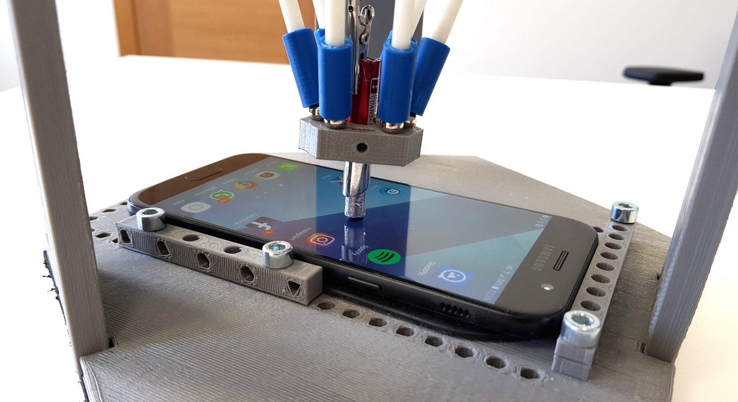
When the first prototype was done we started working on improvements, because we noticed that the moving platform was very heavy and often detached itself from other parts. Replacing metal bearing balls with neodymium magnets solved problem with detaching. However, the platform still was too heavy, so we printed out plastic rods and replaced the metal ones. This finally solved issues with unstable moving platform. Now Tappy can Tap and swipe more precisely.
Next issue was determining correct z-index value for contact point. Since calibration usually gave different values for each corner we had to choose which one to use. Lowest value would assure that Tap always succeeds, but sometimes might penetrate the screen too much. Highest value would be safer for screen, but might not succeed with the tap. As a solution we used lowest value so that the tap always succeeds and implemented stylus a pen with a spring so that even if it goes too low, it won’t damage the device’s screen.
To make sure that device stays in place we placed a simple car antislip mat on the base platform.
These are just a few of the improvements. There are a lot of things that we plan to improve in future. The platform needs to be redesigned to make it more stable and we plan to add some LED’s as well. You know, to make this robot much cooler 🙂
Electronics
For servo motors we chose to stick with proposed Hitec HS-311, because they have good price/performance ratio and do their job pretty good.
But for microcontroller we decided to replace Arduino Uno with a more compact alternative – Arduino Nano, which is more than enough for our needs. Setting up Arduino Nano is straightforward – just upload “Firmata Standard” sketch using Arduino IDE and you are ready to go. We soldered custom board with a on/off switch for servo motors and connections to Arduino board.

For the sake of convenience we added capacitor as well, so we only need one cable to power both Arduino and servo motors. Finally we added a ground cable running from Arduino to stylus pen so that the mobile device screen registers touches properly.
Backend
Robot’s backend server runs on Nodejs. To make it more scalable we divided all the libraries in separate files. For communication with the Arduino board we are using johnny-five library. We tried to setup Nodejs server on Raspberry Pi to make the Robot completely standalone, but faced several issues with some libraries that are not well supported on ARM processor. We plan to dig deeper on this issue.
For communication with external resources we implemented both REST API and Socket.io Websocket libraries. REST API is more useful when there are just some actions that need to be executed by test framework but Websocket is more handy to synchronize data with the frontend app and exchange calibration data.
The source code is available here – https://github.com/guntiss/tappy
Calibration process
Correct robot and device calibration is very important to achieve maximum precision performance. Calibration consists of two parts:
- Robot arm calibration;
- Testing device calibration.
To be able to calculate end effector’s position in 3D space we need to use kinematic transformations. Therefore we need to calibrate robot arms so that we can set them precisely anywhere from 0° to 90° angle. Arm calibration is done manually by detaching rods from arms and setting all 3 arms to horizontal state (0°) and then to vertical state (90°). This way we can map servo motor angles with the base. Values are stored manually at calibration file, since this process needs to be done only once unless arms are detached from servo motors.
Next step is device calibration which is necessary to be able to work with testing device screen coordinates. Thus we need to map two different coordinate systems – robots working plane with the device screen.

The problem we faced with device calibration was that we needed to install a custom application on the test device to calibrate it. It was really inconvenient, which is why we developed a browser based calibration solution, because every device has a web browser already installed. The process is pretty simple – there is a running Nodejs web server on backend with socket.io listener and on the mobile device we just navigate to the calibration page.

Calibration page contains simple javascript code that registers any tap on screen and sends tapped coordinates to server through websocket connection. Some information about device, such as browser version, screen resolution is sent as well. This way we don’t have to install anything on the testing device and calibration can be done in seconds by just pressing “Calibrate” button on screen. Additionally, it supports both Android and iOS and probably even other OS devices. Calibration is done completely automatically – the algorithm taps three points on the screen and stores received coordinates in the calibration file. This is really convenient because calibration must be repeated every time we change the device or its position on the base platform.
Test Automation With Tappy
We came up with two use cases for this robot:
- Record and play automation for battery usage testing;
- Appium test executor.
Since we do a lot of battery usage testing for mobile applications, there are some prerequisites for test results to be reliable. Firstly, there must not be additional software installed on the device that could impact test results. Secondly, test actions must be performed at perfect timing so that the test results are comparable. That’s why manual human testing wasn’t satisfying for such tasks. Main requirement for developing the “Record and play” tool was that it had to be easy to use and simple yet powerful.

It consists of a real time screenshot from the device which is synchronized through ADB. Actions can be recorded by clicking on the image – they are immediately added to the script editor. Scripts run on JavaScript, thus actions can be looped or executed at specific time intervals easily.
The problem with the “record and play” tool is that we don’t have much feedback from the device regarding test results or what is happening on the screen other than the screenshot. That’s why we implemented Tappy as a test executor for our Appium tests. All we had to do was rewrite Tap and Swipe methods to send REST API call to Tappy’s backend.
Rewritten function that uses REST API to invoke Tap action on robot:
def tapster_tap
loc = calc_element_position
p loc
post_data = Net::HTTP.post_form(URI.parse('http://' + Tapster::IP + '/tap'), 'x' => loc[:x], 'y' => loc[:y])
puts post_data.body
end
Huge advantage of using robot instead of pure software automation is that we can access all system functions. For example, we can put an application in the background, switch to another application, change system settings and even type on the screen keyboard, which sometimes can’t be done or is very difficult with just software automation.
What did we learn?
While building this robot we gained a lot of experience – how to 3D print, customize 3D models, assemble the robot, implement kinematics, etc.
This is a great project with which to improve technical knowledge. We got to work with hardware and software and we are happy to have built this robot ourselves!
There still are a lot of things we plan to improve for this project, so stay tuned!
Unexpected Use of the Robot
Some time later, when we had built another robot our colleagues from the marketing team noticed our creations. They thought it was very interesting and took it to various conferences where the company participated. The robot was an absolute star and brought a lot of attention. People came over and wondered what it can do and what technology was used to build it and run it. That is how Tappy became famous! 🙂